
1 Quick overview
A Raymond mill is a pendulum roller mill that grinds bulk mineral feed—limestone, talc, barite, kaolin, gypsum—into fine powder (typically 45–200 µm). Its reputation for reliability and low specific energy makes it the default “finishing” stage in thousands of filler, cement-additive, and fertilizer lines.
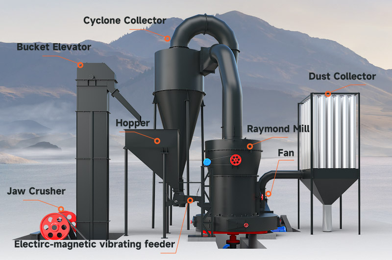
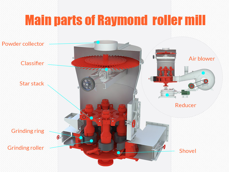
2 Main assemblies and what each one does
| # | Component | Function | Typical wear parts |
|---|---|---|---|
| 1 | Raw-feed hopper & belt feeder | Meters crushed ≤25 mm stone into the mill at a constant t ⁄ h rate. | Rubber belt, skirt seals |
| 2 | Base frame & volute housing | Rigid cast-iron chassis that supports the grinding ring and forms a scroll-shaped plenum for air–material flow. | Housing liners (option) |
| 3 | Grinding ring (bull ring) | Fixed circular track inside the housing. | Ring segments (high-Mn steel, Ni-hard) |
| 4 | Pendulum grinding rollers (3, 4, or 5) | Free-swinging arms press the rollers against the ring with centrifugal force; each roller journals on oil-lubricated bearings. | Roller shells, journal bearings |
| 5 | Ploughs / scrapers | Mounted on the same shaft as rollers; lift fresh feed into the grinding zone. | Plough blades |
| 6 | Central vertical spindle (main shaft) | Drives the rocker arms; coupled to gearbox and 60–150 kW motor. | Thrust bearings, oil seals |
| 7 | Air inlet & hot-gas duct | Primary airflow (ambient or 120 °C kiln off-gas) carries ground material upward and flashes off moisture. | Inlet dampers |
| 8 | Dynamic classifier (turbo separator) | Spins at 600–1 200 rpm; fines (< setpoint) pass on to cyclone, coarse rejects fall back to ring for further grinding. | Classifier blades, drive belt |
| 9 | Cyclone collector | Decouples product from conveying air; > 99 % of fines drop to rotary valve. | Cone liner (erosion) |
| 10 | Bag-filter or wet scrubber | Final dust capture before fan; keeps stack < 20 mg m⁻³. | Filter bags / cages |
| 11 | Induced-draft (ID) fan | Pulls 5 – 12 m³ kg⁻¹ of air through the whole circuit; sets internal “air velocity grind pressure.” | Impeller, fan bearings |
| 12 | Rotary airlock & screw conveyor | Discharges powder into silo while maintaining system vacuum. | Rotor tips, screw flight |
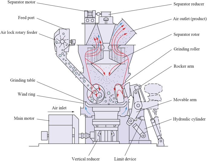
3 How the process flows — step-by-step
Metered feed Crushed < 25 mm rock drops from the hopper onto the belt feeder and into the volute housing.
Grinding zone Ploughs scoop material up under each pendulum. The centrifugal force (~ 35 g) flattens particles between the spinning rollers and the stationary ring, generating compression + shear that shrinks them from millimetres to tens of microns.
Air sweep & drying Hot or ambient air enters below the ring, picking up fines and evaporating surface moisture (1–4 % H₂O typical).
Classification loop The rising air–solids mix enters the dynamic classifier. Rotor speed sets cut-size: faster rpm → finer product. Coarse grains hit the vanes, lose momentum, and fall back; fines follow the air path.
Product collection Fines leave the classifier, spiral through the scroll volute to the cyclone, drop out, pass the airlock, and are conveyed or bagged.
Dust polishing & exhaust Residual dust is trapped in a bag-filter; the cleaned air exits via the ID fan and stack.
4 Key operating levers
| Parameter | What it influences | Typical range |
|---|---|---|
| Classifier rpm | Product fineness | 300 rpm (90 µm) – 1 200 rpm (45 µm) |
| Airflow (m³ h⁻¹) | Transport velocity, drying, throughput | 1.5 – 2.0 × stoichiometric for moisture load |
| Roller pressure (via ring speed) | Mill power draw, top-cut control | 130 – 180 m s⁻¹ tip speed |
| Feed rate (t h⁻¹) | Capacity vs. recirculation load | Adjust to keep ∆P mill ≤ 800 Pa |
| Inlet gas temp. | Moisture limit, bag-house protection | 40 °C for dry feed; 120 °C max |
5 Advantages and typical performance
Particle-shape preservation – compression grinding keeps talc plates intact (lamellarity) better than jet mills.
Energy – 10 – 15 kWh t⁻¹ at D97 ≈ 45 µm (half that of ball milling).
One-pass drying – handles up to 5 % free moisture with 120 °C preheated air.
Low wear cost – roller and ring change intervals of 6 000–8 000 h on normal hardness ores.
6 Common troubleshooting snapshots
| Symptom | Likely cause | Quick check |
|---|---|---|
| Coarser product than set-point | Worn classifier vanes or low rpm | Tachometer on rotor, inspect blade tips |
| Mill over-pressure alarm | Plugged bag-house or excessive feed | ∆P across filter; cut back feeder 10 % |
| High power, low throughput | Ring/roller wear flats | Measure ring groove depth; schedule liner swap |
| Hot product (>90 °C) | Too little airflow | Fan damper position, inlet temp vs exhaust |
7 Integration tips for a filler line
Magnetic separator right before the mill removes tramp iron → protects roller shells.
Screw-feeder with loss-in-weight control stabilises ∆P and product fineness.
Inline surface-treatment reactor (e.g., stearic-acid spray) can bolt to the discharge screw for instant coated talc.
Real-time particle-size probe in the recycle elevator automates classifier-rpm trim.
8 Rule-of-thumb design data
| Parameter | 3-roller 3216 mill | 4-roller 4121 mill | 5-roller 5125 mill |
|---|---|---|---|
| Ring diam. | 830 mm | 1280 mm | 1600 mm |
| Motor power | 55 kW | 110 kW | 150 kW |
| Talc capacity @ D97 = 45 µm | 2 t h⁻¹ | 5 t h⁻¹ | 9 t h⁻¹ |
(Figures vary by OEM; for FEED ≤ 2 % H₂O.)
9 Key take-aways
Raymond mills grind by pendulum roller compression, sweep-dry the powder, and self-classify in one compact circuit.
Classifier speed, airflow, and feed rate form the three-way throttle that sets fineness and capacity.
Proper magnetics, liner maintenance, and bag-filter hygiene keep uptime high and cost per tonne low.
Master these fundamentals and a Raymond mill becomes a dependable backbone for any mineral-filler processing plant.